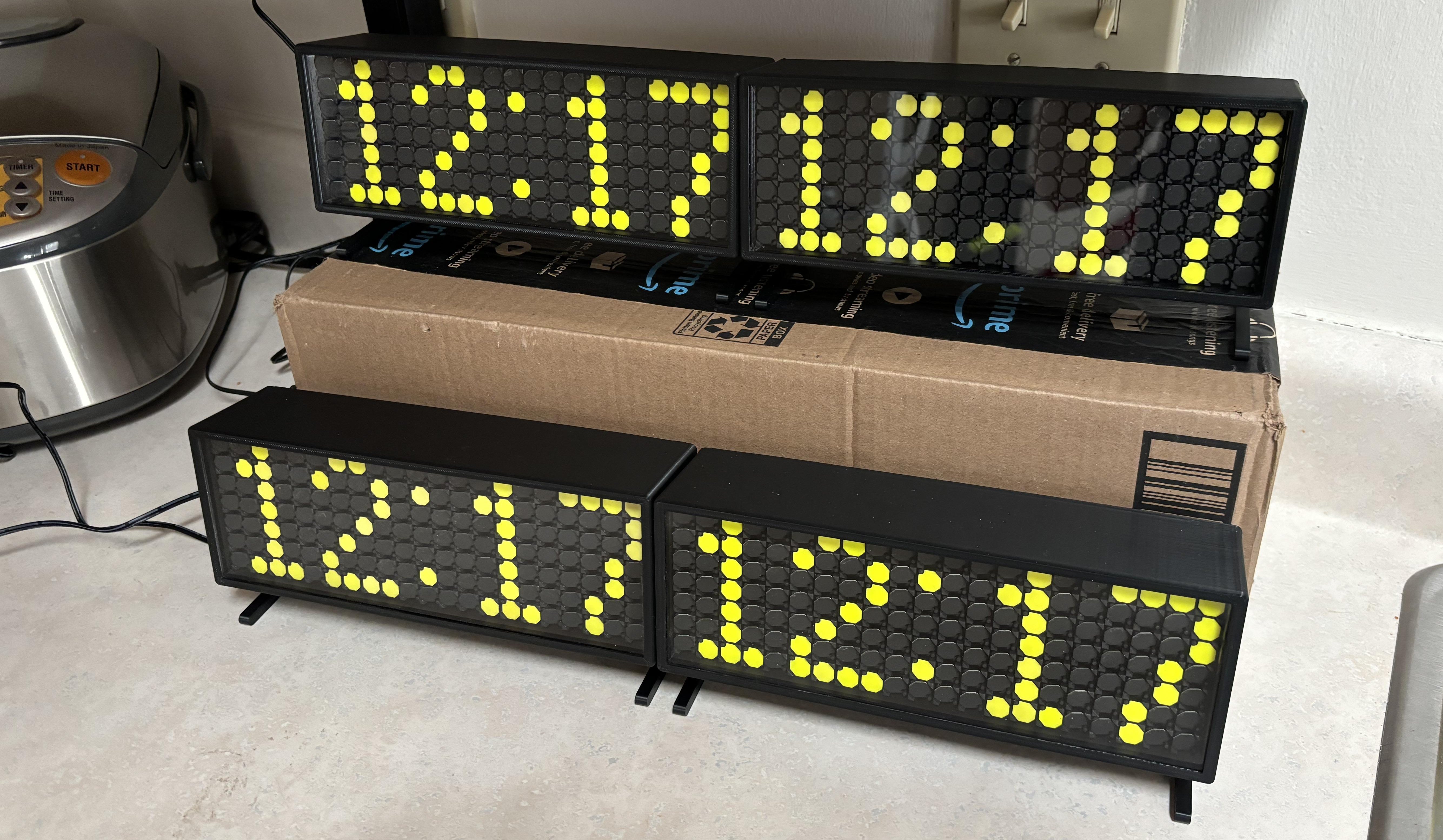
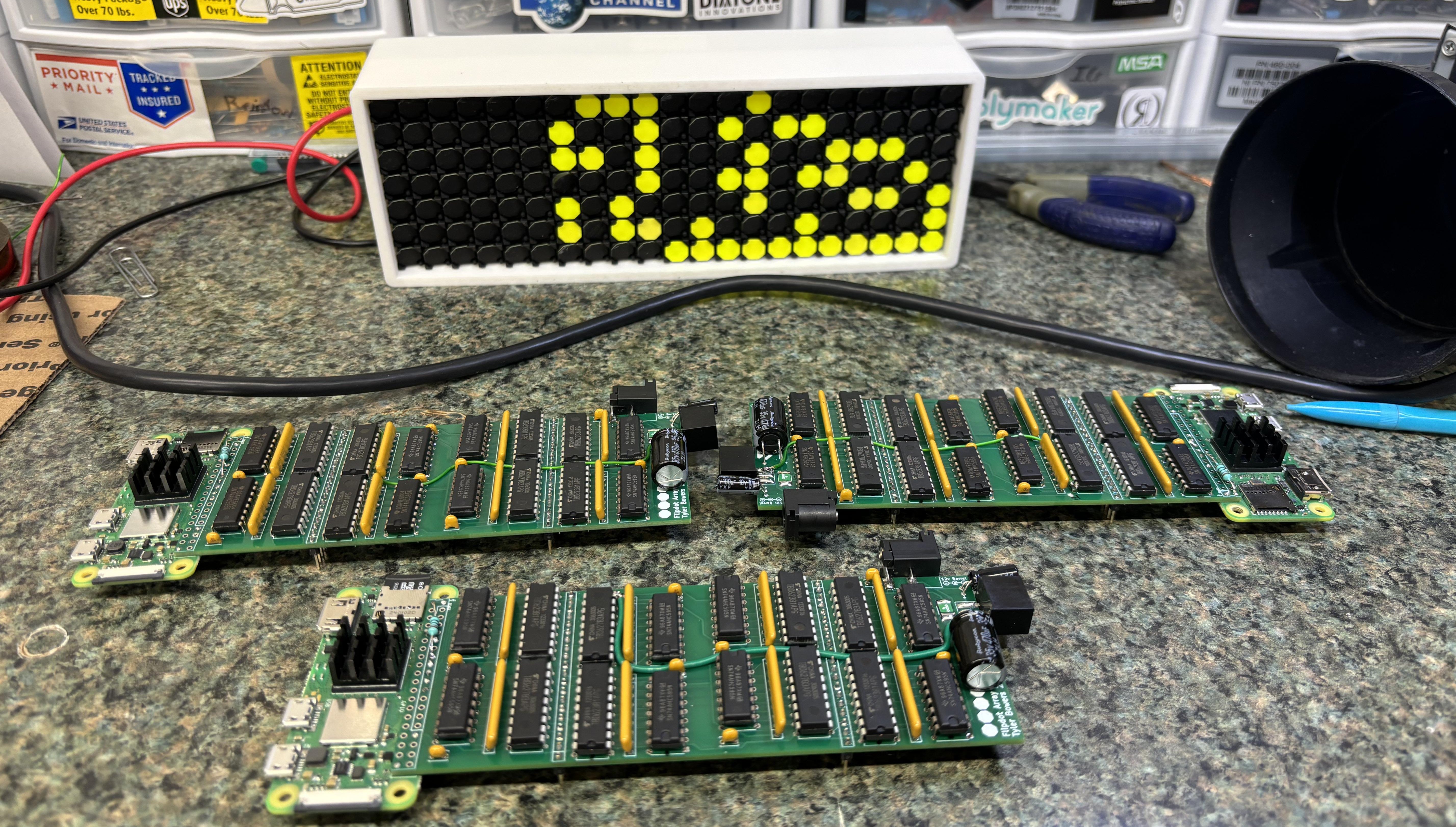
If you have seen my other post about the Luminator flipdot display you can understand why I would want a display that is shorter than 6ft long. I wanted a tiny display that could sit on a desk.
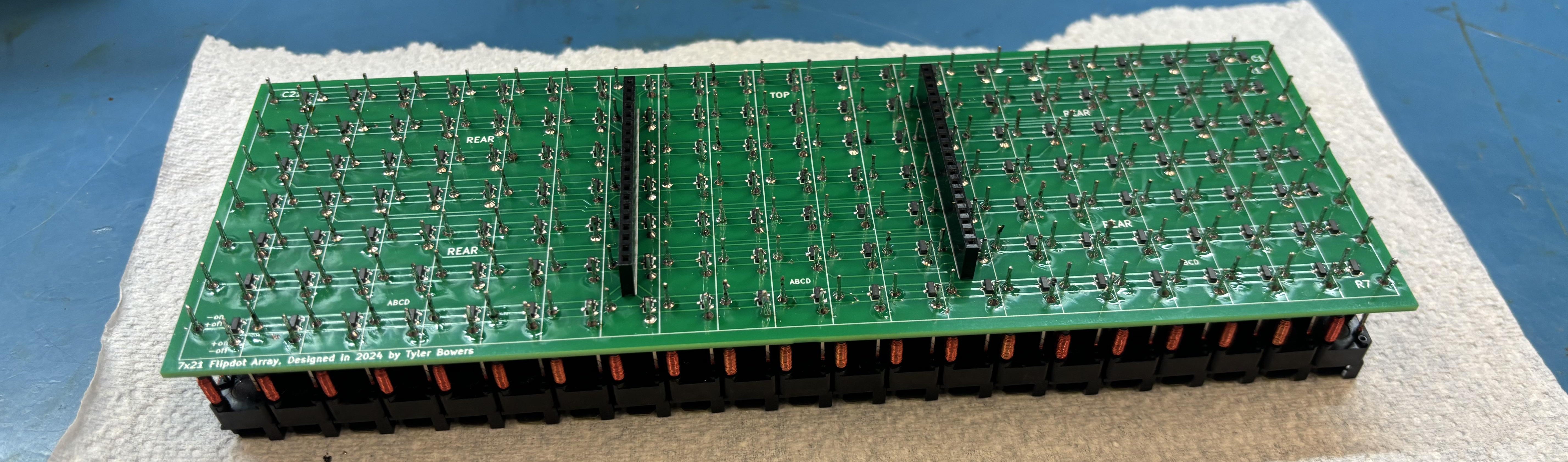
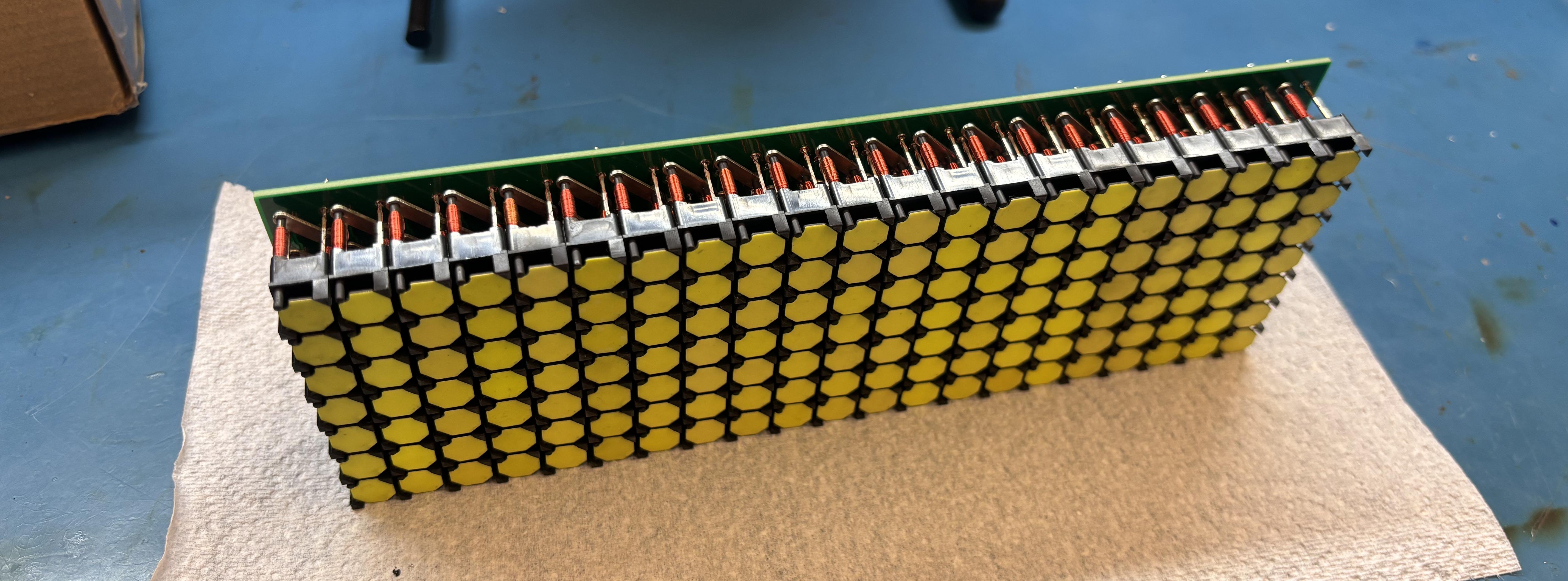
For this project all I used 21 1x7 flipdot arrays, I had to design the array PCB, controller PCB, enclosure, and software. The Github repo for this project is here.
Upclose during Game of Life Simulation:
The Final Product:
I got the flipdots NOS from eBay, specifically from Portugal. Initially I ordered enough for 1 display and some extra, but I ordered more, enough for 4 displays, for some friends. Initially I had a custom PCB made by JLCpcb for a 7x7 array:

After some preliminary testing with the test board I decided to make the full board as I felt confident that my design would work. The controller works similarly to my Luminator one, except there is only one shift register chain that controls both the rows and columns. To toggle a dot, one High is sent to the row, and one Low is sent to the column, or vice-versa. After designing the array board and controller board I had them printed, but it was up to me to assemble them (around 12 hours of soldering total).
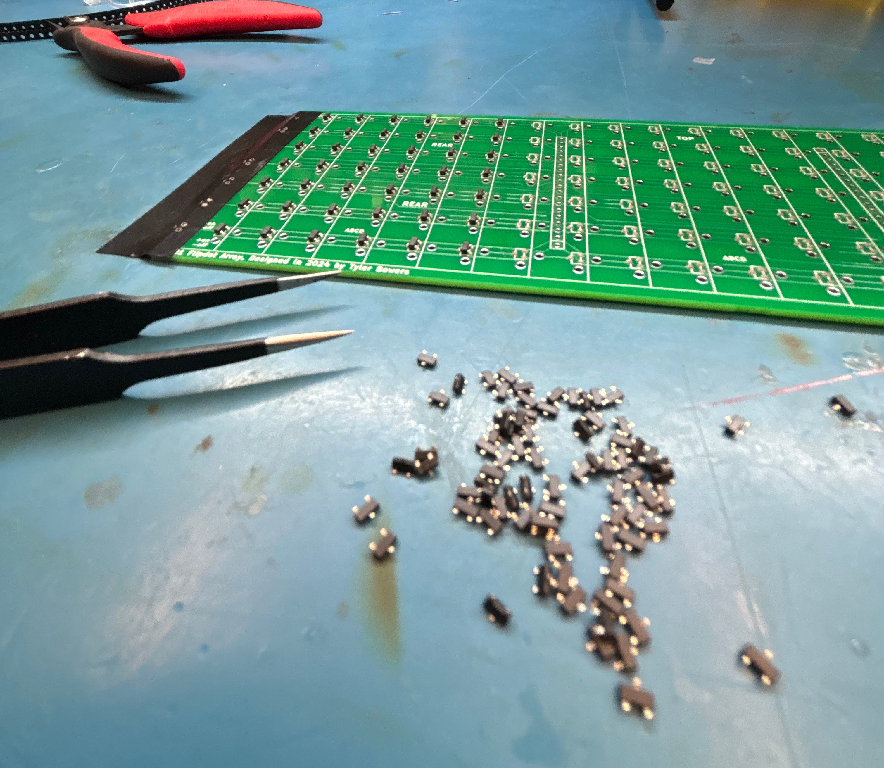
Timelapse of placing diodes:
Timelapse of Placing flipdot arrays:
 Controller Board
It was then as simple as printing a test case and connecting a power supply (and writing some software).
I also built a simulator so I didn't have to rewrite the software every time I wanted to test it:
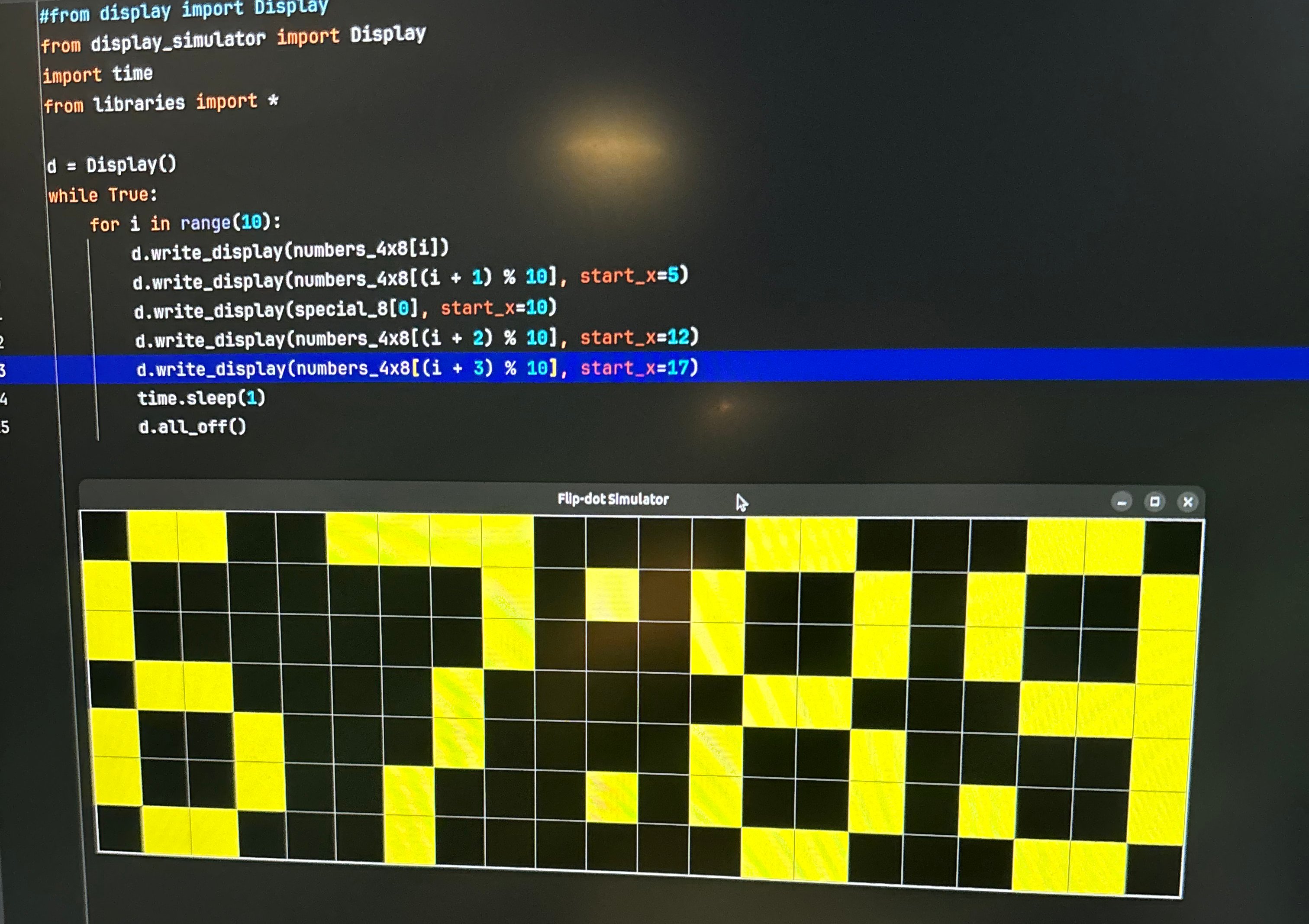
Here is the code to write a single dot, I've added some additional comments:
void write_dot(int x, int y, bool state, bool force = false) {
        // Write dot at x, y with state and don't check shown if force
        _disable();
        _clear();
        // Simple bounds check
        if (!(x >= 0 && x < 21 && y >= 0 && y < 7)) return;

        // What will be sent to the shift register chain
        unsigned long long serial_data = 0;

        //compare with the known state avoids unnecessary writes
        if (state && (!(shown[x] & (1ULL << y)) || force)) {
            serial_data |= (1ULL << y);  // Set row
            serial_data |= (1ULL << (x + 24 + (8 * (x / 8))));  // Set col
            shown[x] |= (1ULL << y);
        }
        else if (!state && ((shown[x] & (1ULL << y)) || force)) {
            serial_data |= (1ULL << (y + 8));  // Set row
            serial_data |= (1ULL << (x + 16 + (8 * (x / 8))));  // Set col
            shown[x] &= ~(1ULL << y);
        }

        // if there is a change to the state of the dot
        if (serial_data > 0) {
            //printf("%d %d %d %llu\n", x, y, state, serial_data);
            for (int i = 63; i >= 0; i--) { // manual writing of the serial data
                digitalWrite(_ser, (serial_data & (1ULL << i)) ? HIGH : LOW);
                digitalWrite(_srclk, HIGH);
                digitalWrite(_srclk, LOW);
            }

            // Move data into registers
            digitalWrite(_rclk, HIGH);
            digitalWrite(_rclk, LOW);
            digitalWrite(_ser, LOW);

            _enable(); // "flash" the display (toggle the coil to flip the dot)
            this_thread::sleep_for(chrono::microseconds(150));
            _disable();
        }
    }
The full code can be found here. You will notice that I am using PyBind to expose the API to Python. Sending the state of the display into C++ allows for quicker serial writing. On the raspberry pi using C++ to write the GPIO pins can be very quick (especially compared to pure Python).
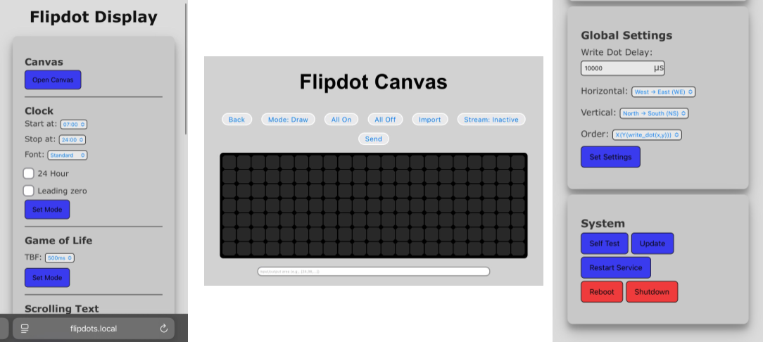
The flipdot software uses runners which have a setup function and an update function. Each runner can be thought of as a mode, these are used with a fastapi frontend. There is also a streaming function where you can live draw to the display. The normal modes are clock, weather, game of life, scrolling text, and date. From the software you can also update itself which pulls the latest from the github repo.
That is essentially it, this short post doesn't cover everything like making fonts from scratch, if you wish to see more of the project, check out the github repo.
Here is it as a clock: